Your cart is empty.

- Quick View
- Choose Options
CAN Power Module
$99.90
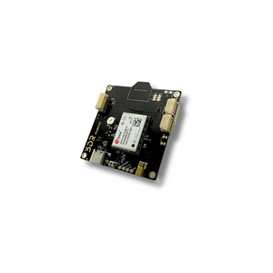
AP_Periph CAN Node — Second Generation with Increased Flash Space.
View Full DocumentationThe CAN Node F303 is a product of a collaborative effort with ArduPilot, stemming from a shared ambition to establish CAN peripherals as a standard in the drone community. This second iteration offers increased flash space for expanded capabilities.
Featuring AP_Periph firmware with a CAN bootloader for effortless updates through the same port. Users can configure onboard parameters with specific CAN Node IDs or opt for auto-allocated IDs. The hardware design is free and open-source, enabling contributions to the DroneCAN peripheral domain using a proven CAN/MCU interface.
The DroneCAN Node allows seamless conversion from UART / I²C / SPI / GPIO to CAN, leveraging the ArduPilot driver library. It is plug-and-play compatible as a GPS and Magnetometer by simply connecting the 6-pin GH connector from any compatible GPS module — instantly transforming it into a CAN-GPS.
Update firmware effortlessly through the same CAN port — no additional hardware or tools required.
Seamlessly convert legacy sensor interfaces to DroneCAN — leverages the full ArduPilot driver library.
Connect any compatible 6-pin GH GPS module and instantly transform it into a CAN-GPS with magnetometer support.
Set specific CAN Node IDs manually or use auto-allocated IDs for flexible multi-device CAN bus configurations.
Free and open hardware design — contribute to the DroneCAN peripheral ecosystem using a proven CAN/MCU interface.
| MCU | STM32F303 ARM Microcontroller |
|---|---|
| Firmware | AP_Periph |
| Protocol | DroneCAN (UAVCAN) |
| Compatibility | ArduPilot, PX4 |
| Country of Origin | USA |
| JST-GH Ports | GPS Port (UART + I²C), I²C Port, 2 × CAN Ports (shared) |
|---|---|
| Solder Pads (bottom) | 1 × SPI (2 CS), 2 × ADC, 3 × GPIO, 2 × UART, 1 × I²C |
Make sure you are using the latest version of Mission Planner with the following firmware versions or newer:
If your controller has more than 3 internal compasses, disable the least important one.
On the autopilot parameters via Mission Planner set:
Then access CAN Node parameters via:
Mission Planner → Initial Setup → Optional Hardware → UAVCAN → SLCan Mode CAN1 → Parameters
Wait ~1 minute, then set one of the following:
Mission Planner → Initial Setup → Optional Hardware → UAVCAN → SLCan Mode CAN1 (or 2)
From there you can access CAN Node parameters and change the default node address among other settings.
If a longer cable is required, you can purchase the MRC0220 4-PIN JST-GH to 4-PIN JST-GH cable in 300 mm or 600 mm lengths.
| SKU | M10042 | ECCN | EAR99 |
| Country of Origin | USA | Current Revision | A |